I have done a lot of work on the recovery systems since the last update, and I do not have pictures at this time. Due to the higher weight of the rocket than I anticipated, I purchased a 70" Top Flight parachute for the main. I also purchased new chute protectors, a new 24" pilot chute, and a new 24" X form drogue chute. I realized that the technique for deployment of the main that I showed in my last post was extremely risky because it would allow the main to begin to open with the nose cone and pilot chute above it, in a position to fly through it. That being said, I will simply be "free bagging" the nose cone on the first flight which means I will have 2 pieces to recover. I have also prepared a 3 gram main charge for a ground test and a 2 gram drogue charge to ground test the ejections before the first flight.
Below is the additional progress (with pictures) since the last update.
Installing Rail Buttons
The rail buttons are the guides that the rocket slides onto the launch pad with. There are 2 standard sizes: 1" (called 1010) and 1.5" (called 1515) rails. Since this rocket is small enough for 1" rails, but may eventually fly on M motors (and launch pads for M motors generally have the bigger rail), I decided to make the rail buttons removable so I can accommodate either size. That way, I can fly it at the minimum "safe" distance away for any motor.
I mounted the two lower rail buttons on the forward and aft centering rings of the motor mount. This meant that I had to do some tricky aligning to ensure that the holes in the body tube were in the exact spots that coincide with the hex nuts epoxied in place to take the rail button hardware. I may use a third rail button. If I do, it will be attached to the electronics bay, which is how I did it in Positive Ascent.
.JPG)
I used a card between the fins to mark the exact center. Then ran a string to the very tip of the nose cone. By eyeballing down the length of the rocket, I could easily set the string so it was exactly straight. This is what I used as my reference to mark the locations for the two rail buttons.
.JPG)
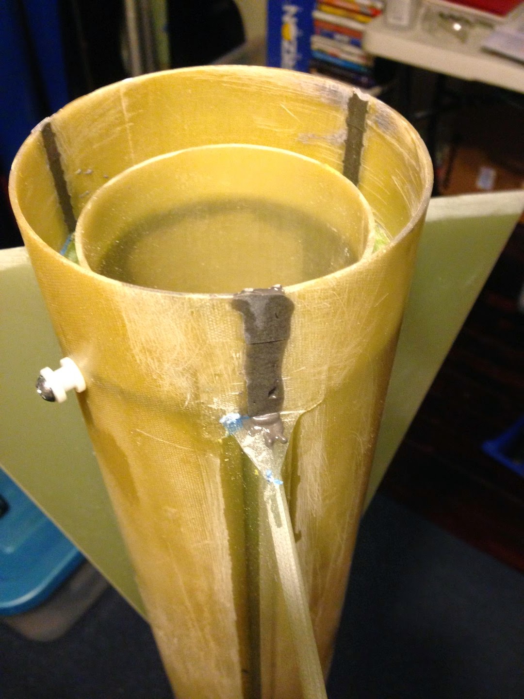
The tape is marking where the centering ring is, and the nut was used to locate where to drill the hole through the body tube. By allowing the drill to go beyond the body tube to nick the motor mount tube, I was able to mark exactly where to tack glue the hex nut on the centering rings.
.JPG)
The forward rail button tack glued in place with the 8-32 hardware sticking out to adjust the angle of the nut to ensure it's square. I used a piece of straw between the nut and motor tube to seal the threads and space behind it from epoxy.
.JPG)
I built up a tape barrier around the nut. I used this space to fill with epoxy, which I had mixed with milled fiberglass for strength.
.JPG)
This is the forward rail button mount, complete with the large chunk of epoxy to keep it solid.
.JPG)
Same process for the aft rail button mount.
.JPG)
Completed aft rail button mount.
.JPG)
Everything lines up beautifully. Here are the 1515 rail buttons installed.
+(Large).JPG)
Here are the 1010 rail buttons installed. It takes less than a minute to change them.
Motor Mount/ Fin Can
I finished up the fin can assembly. This required completing all of the JB Weld fillets and finishing the shock cord mount.
.JPG)
All the gray is the JB Weld fillets.
.JPG)
The shock cord mount is finished. I saturated the knot and trailer with 5 minute epoxy. Note the electrical tape wrapped around the shock cord where it lies against the end of the motor mount tube. This will prevent the sharp edges of the fiberglass tube from slowly wearing the Kevlar strands.
Fin Can Installation
To install the fin can into the body tube, I had to ensure the JB Weld and epoxy had good surfaces to bond to. This meant a combination of 100 grit sandpaper and using the end of a needle file to scrape and sand all areas inside the body tube, on the outside of the motor tube.
.JPG)
The sanded internal fillet and future fillet locations.
.JPG)
The three centering ring locations, and the areas along the fin slots, all roughed up.
.JPG)
I used a band of tape and many rubber bands to hold the aft portion of the body tube against the aft centering ring.
.JPG)
Verifying that the JB Weld hasn't leaked past the centering ring.
.JPG)
Looking into the forward end of the body tube. You can see that the JB Weld did a good job of filling in the space on top of the centering ring. Hopefully, enough bonded to the body tube as well.
Electronics Sled
I thought I had finished the electronics sled, but I decided it couldn't hurt to add some reinforcement, especially for potentially ridiculous G loads. The J1520 for the first flight will actually pull over 20Gs, which is kind of a lot for a rocket of this size, but I'm confident it can take it and much more.
Since the two rotary switches are armed through small holes in the airframe tube , it was very awkward trying to line the screwdriver up with them. I made some simple (not so elegant) cones from index cards to guide the screwdriver to the switch. It works really well.
.JPG)
Showing one switch with the cone, one without.
.JPG)
Both cones glued in place.
.JPG)
The custom (end ground down some) screwdriver for arming the altimeters.
.JPG)
I added a foam block and epoxied the power wires to it. This will ensure that the wires can't pull out from the altimeters during acceleration.
.JPG)
Two foam blocks on the back of the board. These run from the switches, through the board, to the switch terminals on the altimeters. Again, these blocks are to reduce stress on the wires and switches during acceleration. The orange block is the 9 volt batteries taped in. Since this picture was taken I have also added a zip tie around the forward end of the batteries for extra security.
Internal Fillets
To create the internal fin/ body tube joints, I masked the area of interest on the outside of the rocket, then drilled holes at about the middle of the fin length through the tube. I made small funnels out of card stock and poured about 1 ounce of West Systems epoxy into each hole. I did either side of one fin at a time. Once all the epoxy was in place, I taped over the holes and set the rocket so the epoxy would run and settle into the intended joint areas.
.JPG)
.JPG)
External Fillets
To create the external fin fillets, I masked off the area and poured 1/2 ounce of West Systems epoxy into each joint. I leveled the rocket to allow 2 fillets at a time to form into the correct spots. This technique gives very nice fillets except for the ends, where the epoxy forms flat "walls" against the tape that will have to be ground away with a Dremel tool.
.JPG)
Aft end of a fillet taped off.
.JPG)
Forward end of a fillet taped off.
.JPG)
Both fillets ready for epoxy.
.JPG)
Epoxy is poured into each fillet.
Body Tube Slots
I used JB Quick Weld to fill in the slots at the end of the airframe tube. I'm not sure if they are strong enough, but they are purely cosmetic anyway.

I notched each slot in several spots with a file to provide more surface area for the JB Weld to bond to. You can see the saw tooth shape of these notches.

Motor Retainer
I mounted the 75mm Slimline motor retainer. I used regular cure JB Weld for this step.
.JPG)
No comments:
Post a Comment