Wednesday, June 30, 2010

Super Weasel Nearly Ready for Finishing

At this point, all of the fillets are done. They are really oversize, and I honestly think the wood of the fins would break before the root of the fin/ body tube joints (this is a good thing).


This is my attempt at motor retention, which is a unique challenge on a minimum diameter rocket. I ran a 100lb Kevlar cord around the drogue recovery harness inside the airframe. The idea is that these cords are small enough that they don't interfere too much with installation of the motor. Once the motor is installed, the cords can be tied around the aft end of the motor, preventing it from sliding out. I've never seen this setup but I think it will work well.


This is the completed aft assembly, including the installed rail buttons. The next step is priming and filling.

Super Weasel

Here's a quick shot that shows what a small supersonic rocket flight looks like:

http://www.youtube.com/watch?v=cCBdECjAM9E

Anyway, I am now calling the rocket the "Super Weasel" due to my intention to fly it supersonic some day.

All of the fiberglass pieces are now applied, and two sections are sanded. The sanding is making them come out what seems to be very nice. Only the first coat of primer will really show the texture.

Also, one set of fillets is done. I used 5 minute epoxy, and dragged a plastic spoon across the epoxy to create the fillet shapes. Frequently dipping the spoon in rubbing alcohol prevents the epoxy from sticking to it uncontrollably and allows a very smooth finish on the fillet.


I also made the drogue recovery harness anchor. It consists of the unused 29mm centering rings from the motor mount kit and a piece of 3/8" tubular Kevlar cord. This assembly will be epoxied in place in the body tube.


On a different note, the weather forecast is looking agonizingly perfect for my level 3 certification flight this Saturday. Take a look - 3 different weather sources can't all get it wrong can they? We will see...

Monday, June 28, 2010

Weasel Progress and Performance Estimates

The third and last piece of fiberglass spanning the fins is now on the rocket. The other 2 pieces are sanded smooth and I've been trying to figure out what to do to make them neater and nicer to finish. What I've come up with is to lay a similar piece of very light fiberglass cloth over the finished pieces. This fiberglass is light enough where I can carefully brush the West Systems epoxy onto it until the entire piece is stuck.

I also will cut these pieces to extend all the way to the edges of the fins, slightly beyond the leading edges at the root of the fins, and to the aft end of the body tube. So far I've finished one of these pieces and I'm confident that it will sand very nicely. 


The red outline is from the previous piece of fiberglass. The light stuff is nearly impossible to see when it's wet but it spans all the way to the edges of the fins, unlike the heavier stuff underneath.

I've also began sanding, filling and priming the nose cone and main recovery bay. Playing around with Rocksim and the colors of spray paint I already have, I have come up with the following simple color scheme:


The only difference is that I plan on doing one fin yellow, and continuing the yellow as a vertical stripe all the way up to the gray coupler tube.

I also have a good idea of the expected performance based on the Rocksim simulations. Here are the 29mm motor simulations:


And here are the 38mm simulations:


It is obvious that anything above a medium impulse I motor will push it supersonic. My goal is to fly it on the I284W. That motor has plenty of white smoke so it would at least be possible to follow for the 2 seconds of the motor burn. I'm pretty sure if I went with a blue thunder motor for the mach flight, it would be impossible to see much of anything because that propellant doesn't put out much smoke.

Thursday, June 24, 2010

Loc-Precision Weasel Progress

Here are the 3 fin roots. I drilled small holes to allow the epoxy to get into the fin and allow a stronger bond.

I also cut and peeled the glassine layer off the tube where the fin root goes, allowing the epoxy to soak into the cardboard, rather than simply resting on the outside and not penetrating the joint.


My setup for applying the fiberglass to the fins and tube joints. Family Guy DVDs provide support. The cardboard object next to the rocket on the DVD is a "pressure jig" I made from extra coupler tubes. The idea is that this piece gets weighted on the tube between the fins when the fiberglass and epoxy is drying to make sure the fiberglass is tight on the tube.

 Fiberglass, ready for application onto model.

  The first application of fiberglass. The epoxy is cured is this point. It came out decent. I think it is strong, which is the most important part but it's going to take a lot of work to get it smooth for primer.

The second fiberglass piece. I used West Systems epoxy this time instead of 30 minute Bob Smith Industries. This allowed me to get plenty of epoxy this time. Again, it's strong but it's going to take a lot of sanding and filling to smooth it out. Since I'm going for supersonic, it's important that it's as smooth as possible. It's not just for good looks anymore.

Here's the completed electronics bay. The switch is integrated into the electronics board which will make sliding everything together much easier at launch preparation time. Note how the board has an integrated battery mount, allowing assurance that the battery won't budge on 60+ G launches. For flight, the battery will simply have a few wraps of tape to keep it in place where it rests in the board.

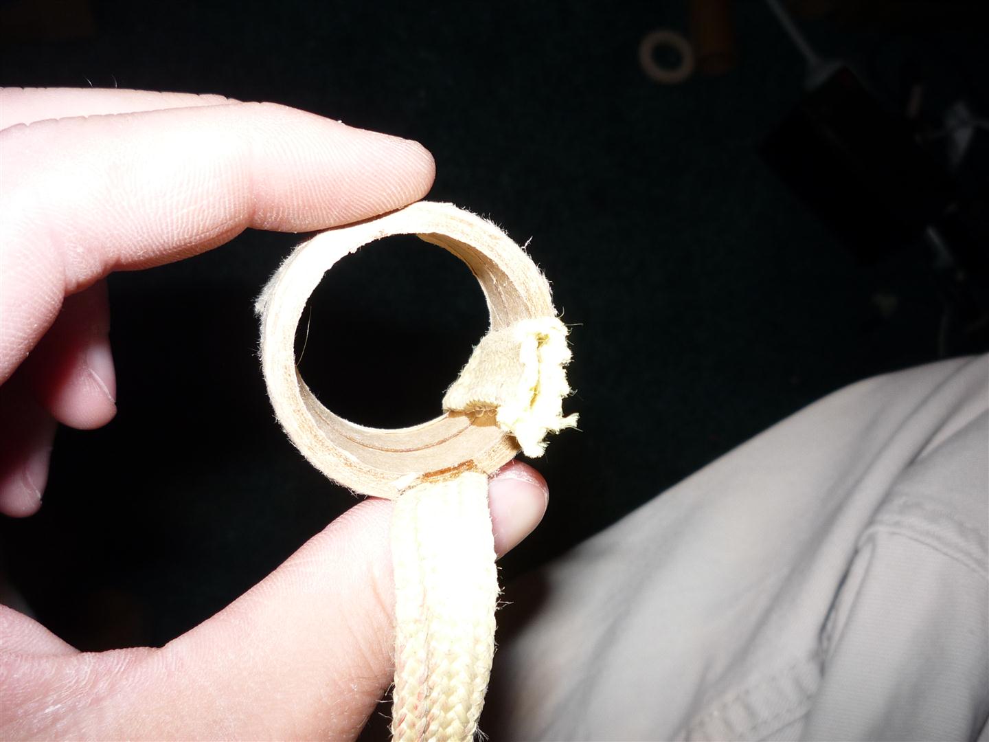
Here's the bottom view. I had to make the white threaded rod guides myself. They are rolled paper tubes that are saturated with thin CA glue for strength. They have generous epoxy fillets to hold them in place on the board.

End of the electronics bay.

The other end of the electronics bay.

Here's the electronics bay fully assembled. One of the threaded rods has threaded couplers and the eye bolts for recovery harness anchors. This design assures that no significant recovery load goes into the bulkheads of the electronics bay. Instead, the threaded rod will take all the load.

Demonstrating that the air sampling hole also functions as access to arm the electronics.

The little plastic piece intended for attaching the recovery harness to the nose cone is notorious for failing. For this reason, I've installed an eyebolt and a generous amount of 30 minute epoxy to hold it in place.

Tuesday, June 22, 2010

Current Rocket Project

Here is my project that I am aiming to finish for the 4th of July launch. It's a minimum diameter 38mm model that will weigh about 1.5 pounds when completed. It's a Loc-Precision Weasel kit that I am modifying by removing the motor mount (to allow bigger motors), adding an electronics bay for altimeter based dual deployment recovery, and fiberglass the fins to the body tube to allow it to withstand speeds approaching mach 1.
 The fins are only taped in place to see the general shape of the model at this point. Stay tuned for more updates soon. Next will be attaching the fins and working on the electronics bay.

First Post

I've just created this blog as an attempt to stop seeming irrelevant by posting model rocket updates on RCgroups, a forum dedicated to remote control aircraft.

Here is the RCgroups link to my level 3 certification rocket, as well as some other projects:

http://www.rcgroups.com/forums/member.php?u=102075

Who knows, maybe I will end up using it for more than just posting rocket stuff.