I have never built a launch tower before so this was a little bit of experimentation. I'm fairly content with the results and I think it's sufficient for one flight.
The base was a scrap piece of plywood from work.
The base of the supports was built with a chunk of 2" thick balsa sandwiched with triangles of 3/8" aircraft ply. The most difficult part of the build was the holes for the 1/4" guide rods. Without a drill press and without a decent way to mark their locations, it was an iterative process. Therefore the holes are bigger than they should be but a bunch of epoxy takes up the rest of the space in the holes.
Blind nuts through in the base and 1/4-20 bolts hold the guide assembly to the base. It made a lot of sense to make this part removable for transporting it.
The bands of blue tape around the rocket were used as spacers to leave a small clearance between the rods and the rocket while the epoxy cured in the support guide holes.
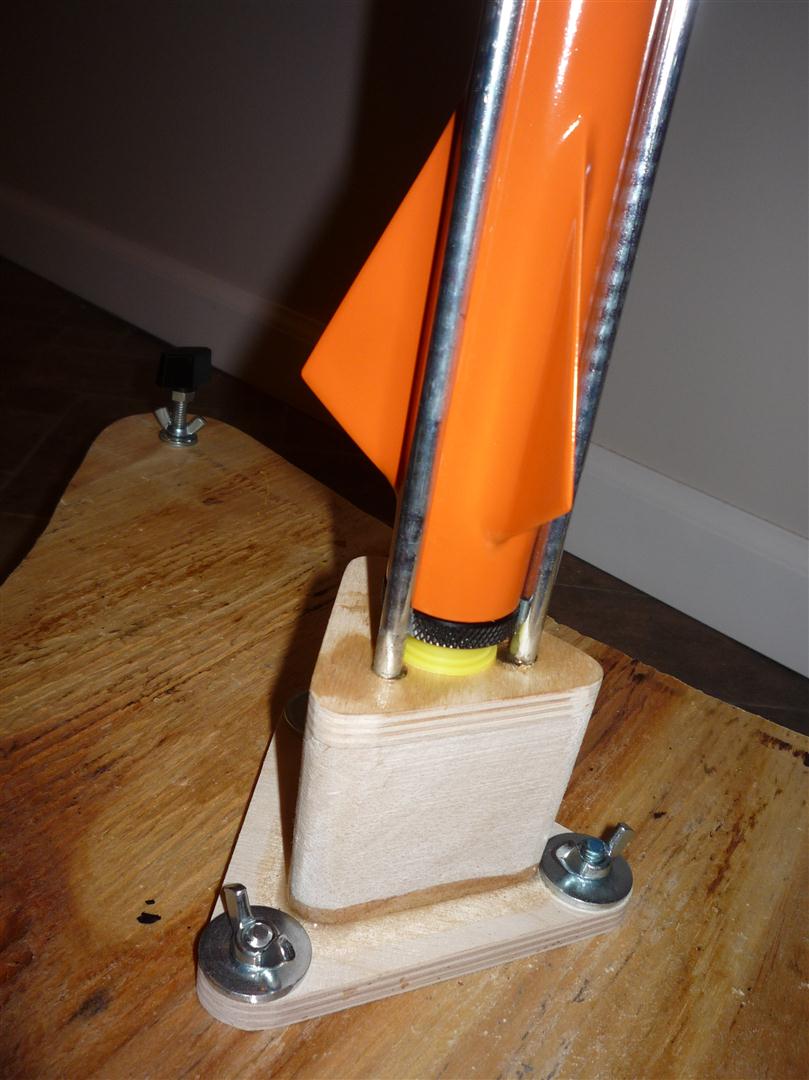
The completed and mounted guide assembly. I decided to use threaded studs and wing nuts to make attaching it very quick and simple.
It turns out that the 3 rods by themselves were way too flexible to safely guide the rocket out of the launch pad so I had to build an upper guide support ring. I used a scrap piece of 4" diameter phenolic coupler tube and 1/16" ply braces. I epoxied this assembly to the top of the guides, which prevents them from bending.
The base itself is adjustable to accommodate the field's unevenness. There are 3 threaded legs which go through blind nuts. It is simple to adjust with the knobs, and the rods lock in position with the wing nuts. It will take 2 people and a pair of levels to properly set it up at the field. Without the guide assembly in place the threaded studs are visible in the middle of the base.
Here, the pad is fully assembled and the legs are nearly fully extended. They will allow up to 4 inches of unevenness, which will be plenty to accommodate the field.
I will do a new post showing the finished rocket in the launch pad.