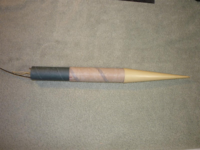
At this point, the rocket is fully constructed. All that is left is to prime and paint it, and drill the air sampling holes for the altimeter. I'm excited to use the Pnut altimeter for the first time in this rocket. It's tiny, yet records all flight data, including altitude, velocity, and temperature, and plots it all out versus time with some simple software.
Getting both the tracker and altimeter mounted securely in the payload tube was the biggest challenge for this rocket. Here's how it was done:
The blue tube is the coupler tube, and houses the electronics. The tracker and altimeter both mount onto the assembly with the 2-56 threaded rods and bulkplates holding it all together. The altimeter mounts into the 18mm tube (left in the structure) and the tracker mounts above it between the rods. The forward end (on the right in the picture) of the assembly is retained with the larger bulkplate against the end of the coupler tube. Therefore, all of the force due to acceleration will be transferred through tension on the rods and into the forward bulkhead.
The tracker's support is a simple spruce brace that slides into position against the rubber pad.
The altimeter keys into the slot in the forward bulkplate at the end of the 18mm tube.
The aft bulkplate then goes on. The rubber pad will lessen the blow of 70+ G's. The Kevlar cord also attaches here.
The aft end of the assembled electronics bay. The tracker's antenna hangs down and gets curled on itself to fit into the airframe.
The assembled electronics bay with the nose cone. The nose is 6:1 conical, and solid urethane. The coupler tube plugs into the booster airframe about 3 inches. This will allow a very nice, stiff joint, aiding to eliminate potentially disastrous flex during the high G acceleration.
The Kevlar shock cord mounted deep in the booster airframe, as far back as possible to not interfere with the long motor casing. (the motor actually just touches the ring that the cord is epoxied into)
Next will be my usual prime, fill, sand, repeat, followed by a bright and simple paint scheme. I still need to build the launch tower as well.


Why do you need to build your own launch tower?
ReplyDeleteI need to build a launch tower because I am not putting any rail buttons or launch lugs on it to reduce drag.
ReplyDelete